Saturday, 21 April 2012

Preparation for FYP presentation


Week 14

Title of the project: Preparation for FYP presentation

Objective: Present the Final Year Project

Content/Procedure:

  • ·         Make sure project function.
  • ·         Study all technical and theoretical of project.


Analysis:

Based on this project, student should know what are learning during doing this project. It including the technical and theoretical of component used and the flowing of work around 2 semesters. Hence, student needs to explain all of question by judges.

Conclusion:

Finally, student should present all of work done to judges. The objective to show what are student had learn around 1 year doing research of project.

Wednesday, 18 April 2012

Design the poster


Week 13

Title of the project: Design the poster

Objective: To design a poster about project description to make publish for audience and judges

Content/Procedure:

·         Project description
·         Objective of project
·         Blog diagram
·         Methodology
·         Result
·         Conclusion


Explanation of Project description

Advancement in technology has brought various development in agriculture industry. This project aims to demonstrate an agriculture waste into organic fertilizer machine for plants by using raw materials. This scheme proposes the mechanical and computerized system to process waste disposal into fertilizer that useful for plants. This will help the agricultural people to recycle the organic waste efficiently.

Objective of project

q  To develop a machine that composes of agriculture waste into    organic fertilizer through the combination of software and hardware.
q  To demonstrate the automation system of the machine that effectively transforms the waste into useful fertilizer.
q  To evaluate the functionality of the machine this can help to save the environment by recycling the organic waste for agricultural application.

Design block diagram

Methodology of project


Record result and analysis

Poster design


Analysis:

Poster is a medium to publish the idea make a project. Student should state all of information such as description, objective, blog diagram, methodology, result and conclusion. During presentation, student should explain the overall of project function depend on project develop, also to show the objective achieve and learn from project. Hence, by complete this project it help student gain the knowledge.


Conclusion:

After complete this work, student have to state all of project information and publish to audience to make them understanding what are project develop for. In the technical side, student knows what the outputs of project produce are.


Monday, 16 April 2012

Design the hard ware


Week 12

Title of the project: Design the hard ware

Objective: Construct the prototype

Content/Procedure:

  • ·         Measure the circuit size
  • ·         Locate at the suitable place of circuit and lamp
  • ·         Design blade at motor to mixing raw material


Analysis:

From the picture, it is a design of the fertilizer machine. In observation, the exiting design product is good and commonly used in industry but in the big scale. For this project, it has been rescale become compact machine, that why it can be used in small industry such as for housewife and the people who are have small garden. Basically, the hardware is same but propose is difference.

Conclusion:

To made new design, designer should note all aspect such as the material used, costing, sizing, item endurance and also their usage. If miss some of part, the design will not completely useful also will take time to develop the new design.

Saturday, 14 April 2012

Compile/get the result


Week 11

Title of the activity:  Compile/get the result

Objective:

  • To obtain this project working based on expected
  • To ensure the project is follow the main objective of this project or not

Content/Procedure:

  • Understand the main objective
  • Get the result based on objective

Objective of project

·         To develop a machine that composes of agriculture waste into    organic fertilizer through the combination of software and hardware.
·         To demonstrate the automation system of the machine that effectively transforms the waste into useful fertilizer.
·         To evaluate the functionality of the machine this can help to save the environment by recycling the organic waste for agricultural application.

Analysis

Based on project, result is taken by rotation motor and time setting. Then, lamp or heater circuit should detect the actual temperature refer to set point. For example, set point of temperature set is 35°c, if temperature detect below than this value, lamp will switch on to produce heat in drum. Also if temperature over for set point, lamp will switch off mean temperature in drum already achieve the set point temperature. Below are the classifications of heat condition
·         0%- lamp ON in turbo condition (100%)
·         50%-lamp ON (50%) and OFF (50%)
·         100%-lamp OFF (100%)

    Relation between set point and actual temperature

   Conclusion:
   As a conclusion, the main objective of this project is achieved when proved by taken the result of this project.


Saturday, 7 April 2012

Run the project


Week 10

Title of the project: Run the project

Objective: Record the data (Input and Output)

Content/Procedure: 


Motor rotate


Lamp heater


Push button


LCD display


Analysis:

Based on the picture, it shows the operation of circuit process. When switch on supply, it show name’s, SP (set point), AC (actual temperature) and αT (time).Set point is the temperature reference and it related with sensor LM35,so if the sensor have a changes it automatically update at LCD screen and if value are below SP ,the circuit heater will switch on to giving heat to make stable condition. Also, push button used to set the increasing or decreasing temperature at set point and time operation. Beside sensor, already locate variable transistor because function as calibrate or voltage reference for circuit. For example, to get the accurate reading of temperature, circuit should set the actual temperature base on the environment. Sensor will be read the actual temperature base on the calibrate setting. DC motor function based on time setting, where doing process of mixing compose material. It not directly rotates because programming’s setting run and stop during operation.

Conclusion:

Circuit operation is the most important to make sure the objective of project achieve. In this work, every circuit already tested and recorded the step operation. On this work, the main part is PIC16F877A because it plays as a heart to control overall operation. So, these circuits already function as expected. 


Tuesday, 20 March 2012

Construct and soldering component

Week 8
Title of the project:  Construct and soldering component
Objective: Build the actual circuit
Content/Procedure: 

PIC circuit


Heater circuit


Analysis:
While doing this circuit, the important thing that must take note is the actual design of component. If the design has a problem of size component, it cannot be match into circuit. From the picture, component can be locating at circuit and have jumper to another circuit. The jumper used to connect the input and output of PIC such as the variable resistor, sensor LM35 and heater circuit. Also, at input terminal (supply) have a connection to give main supply at the circuit.   


Conclusion:
In this work, the difficulty are face when need to locate component. Student should careful to do soldering process because some component have high sensitivity which can burn and cooper will broke if applying high temperature by solder. So, all work must be careful and make sure component still in good condition.


Wednesday, 14 March 2012

Construct circuit board

Week 7
Title of the project:  Construct circuit board
Objective: Etching process
Content/Procedure:
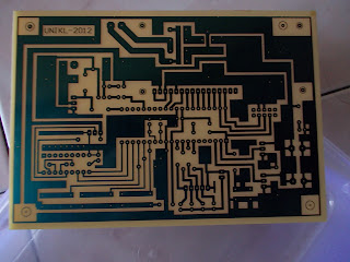
1)    Print the design on transparent paper/stick paper 


2)    Stick the design on PCB board


         3) Etching process


                   4) After etching process


Analysis:
First step of etching is stick the design at PCB board and it should paste all of the carbon because it the way of current flow between component. Next, by using etching liquid the process is to erodible the cooper layer until left only copper line at circuit. Then, clean up circuit layer until look shiny and start process of drill a hole of pin component.

Conclusion:
Etching process is important to make sure all connection will connect between components. So, after this process it should be testing to check the connection of circuit in good condition.


Sunday, 4 March 2012

Design PIC circuit

Week 6

Title of the project: Design PIC and heater circuit
Objective: To build the interfacing circuit between the motor, heater and PIC circuit
Content/Procedure:

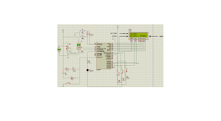
Design circuit by using software

Analysis:
After complete design using proteus, circuit on software will be transform to be an actual circuit. By using Protel Design System, it already locates component and connection of each component. Student should re-check to make sure have no overlapping layer and circuit will be adjust as needed. The important thing, this software will build as an actual circuit, mean component can be place into circuit with component pin can be place at PCB board.
Conclusion:
This circuit is use to connect between the component in circuit. It can be design as expectation of sizes at the PCB board. So, student can print the design and it ready to paste into PCB board.

Monday, 27 February 2012

Run the programming of PIC

Week 5

Title of the project:  Run the programming of PIC
Objective: Record function of circuit
Content/Procedure:
-Check the connection of component
-Burn the program into PIC

Start run program

Setting the voltage reference and LM35

Check push button (increase and decrease)

SP=Set point

Time setting

Circuit Motor

Heater (Led show output to heater circuit)

Analysis:
In proteus, after construct the circuit, program writing will be burn into PIC. Before that, program should be compiling to make sure have no error, if still have an error; program cannot be burn and need some modification. In this case, software will show at which line has a problem, so it make easy to do some correction. If program already complete, circuit can be operate based on the step planning in program such as display name, rotation motor, time setting and input at the sensor(LM53).  


Conclusion:
Based on this work, assemble language play as important part to make the PIC function. Instruction giving refers step planning of circuit operation. It must be related for each circuit because when PIC start operates, each circuit will do their own operation. 

Tuesday, 14 February 2012

Study programming of PIC

Week 4

Title of the project: Study programming of PIC 
Objective: Make the PIC operate
Content/Procedure:

Study pin i/p and o/p

Define port:    A (sensor/heater)
                        B (LCD display)
                        C (Switch)
                        D (DC motor)

Program language:
;===============================================================
;PROJECT TITLE  : WASTE TO FERTILIZER CONVERTER
;===============================================================
                                                LIST P=16F877a
                                                ERRORLEVEL       -302
                                                ERRORLEVEL       -305
                                                #INCLUDE <P16F877a.INC>
                                                __CONFIG          0X3F32

;========================MACRO ==================================
BANK0                  MACRO                                ;CHANGE TO BANK 0
                                BCF                        STATUS,RP0                                                                      
                                BCF                        STATUS,RP1
                                ENDM                                  
BANK1                  MACRO                                ;CHANGE TO BANK 1
                                BSF                         STATUS,RP0
                                BCF                        STATUS,RP1
                                ENDM                  
BANK2                  MACRO                                ;CHANGE TO BANK 2
                                BCF                        STATUS,RP0
                                BSF                         STATUS,RP1
                                ENDM

                               
BANK3                  MACRO                                ;CHANGE TO BANK 3
                                BSF                         STATUS,RP0                                                                                                                                                                                                                                                                      
                                BSF                         STATUS,RP1
                                ENDM
CLOCK_E              MACRO                                                                                ;'E' RISE UP N FALL DOWN
                                BSF                         PORTD,07
                                CALL      t1m
                                BCF                        PORTD,07
                                CALL      t1m
                                ENDM
;===============================================================
;========== VARIABLE ===========================================
;DATA MEMORY ADDRESS =        20h - 7Fh (BANK0)
;                                                         A0h - EFh (BANK1)
;                                                               110h - 16Fh (BANK2)
;                                                               190h - 1EFh         (BANK3)
;===============================================================
;===============================================================
;========== RESET VECTOR =======================================
;===============================================================
ORG                       00
RESET                    GOTO    INIT
;===============================================================
;========== INTERRUPT VECTOR ===================================
;===============================================================      
ORG                       04          
INT                         GOTO    INIT
;===============================================================
;========== INITIALIAZATION ====================================
;===============================================================
ORG                       05
INIT                       
BANK0                               CLRF         PORTA
                                                CLRF      PORTB
                                                CLRF      PORTC
                                                CLRF      PORTD
                                                CLRF      PORTE  


BANK1                               movlw     b'00000101'                         ;PORTA analog input;right justifide;RA3 Vref
                                                movwf  ADCON1
                                                movlw  b'00011111'
                                                movwf  TRISA                                    ;PORTA AS INPUT/OUTPUT
                                                clrf          TRISB                                     ;PORTB AS OUTPUT
                                                movlw  b'10111111'
                                                movwf  TRISC                                     ;PORTC AS INPUT
                                                movlw  b'00000000'
                                                movwf  TRISD                                    ;PORTD AS INPUT/OUTPUT
                                                movlw  b'00000000'
                                                movwf  TRISE                                     ;PORTE AS OUTPUT
                                                               
BANK0
Mulain                               CLRF         PORTB
                                                clrf          PORTD


;=============== MAIN PROGRAM START HERE========================

Analysis:
To write a program, student should know the language of the software used and the expectation of circuit operation. In this work, before writing a program it should be define the step operation at input and output PIC. By referring data sheet PIC16F877A and ASM software, student can plan what are step need such as time setting, input sensor, push button and LCD display. It must be properly step setting because PIC cannot read if the wrong instruction given also the operation may be interrupt. In this case, student already done some adjusted of the program because PIC cannot run as expected. So, the program should be modified until it can run as step planning. After complete writing program, it should be compile to check where the wrong of language and if have no problem, it show the program successfully build.

Conclusion:
Writing the programming is the important part in PIC because it functions as heart to giving instruction of circuit operation. So, all the instruction must be properly write depend on step and transmit at pins which make it operate.